How Do You Know if Toliet Valve Is Threaded or Not
Plan the location of your wall-mounted toilet. Consider the paths of supply and waste plumbing and the wall stud location and spacing when considering the location for the toilet wall carrier frame. Demo the wall structure in this area to expose the wall framing and plumbing.
For your hereafter plumbing, you volition need a 1/2″ cold water supply line to the unit and a iii″ waste product line below the unit of measurement.

Depending on the wall framing in your bathroom, Geberit offers several in-wall tank frame units to fit about traditional wall framing. Our motel bathroom has standard 2 ten 4 woods stud construction which matches the Geberit 111.728.00.1 unit for standard two″x4″ stud wall construction. This unit is designed for ii″x4″ framed walls, but requires a wider, 23 1/2″ stud spread to make room for the water tank in this ii×4 "shallow" unit of measurement. This wider (23 ane/ii″) than traditional ii x 4 stud spacing (fifteen ane/2″) unit will typically crave stud modification to suit the width.
For us, modifying the wall framing was non a large deal as we were in the heart of a total bathroom renovation and could easily revise the framing for the 23 1/2″ broad unit of measurement. In improver information technology's the width, the unit of measurement calls for wall framing load bearing chapters of 880 lbs., prompting usa to double up the studs framing the cavity where the in-wall toilet frame would exist mounted. We also reinforced the studs with Simpson Stiff Tie GA2 gusset plates and structural grade fasteners to help manage the added load on the wall framing.

The in-wall toilet system will require a supply water line and a waste discharge piping within the footprint of the wall cavity. With the walls and floors of the bath open up for our renovation, it was easy for us to add together the exact plumbing nosotros needed for the unit of measurement.
For the toilet waste line, we ran a long sweep (indicated for all drains, especially toilets) four″ to 3″ Sanitary Tee simply nether the unit. A short department of 3″ PVC was passed from this tee through the floor plate leaving a few inches of pipe straight under the framing unit to connect the discharge plumbing from the toilet basin.
To laissez passer through the floor plate of the wall framing, nosotros didn't cut through the floor plate, but merely removed a short section of it (iii″ PVC pipe has the same width (3 1/2″) as the floor plate ii 10 4). To support the cutting ends of the floor plate, I added additional blocking between the floor joists. This extra support under this portion of the wall framing will assist the floor support the weight of the unit of measurement in utilize.
This centered waste pipe location is required for the Geberit unit designed for iii 1/2″ wall depth (2″ x 4″ stud wall). Geberit also has units designed for deeper walls (2″ x half-dozen″ framing) that allow for a side as well every bit a vertical waste pipage path.
For the water supply, I ran ane/2″ copper from the crawl space. I pass this line through the floor plate, forth the left rear of the wall cavity to adjust the forepart-mounted toilet carrier frame.
Mount the wall frame and concealed toilet tank unit in the wall cavity. I used the Geberit 111.728.00.1 unit designed for 2 10 four framed walls. The unit is 23 one/2″ wide.
To outset, I revised the stud cavity width where I planned to mount the unit to arrange the 23 one/2″ width. When framing this cavity, I used double studs reinforced with Simpson Stiff-Necktie gusset plates to help come across the load bearing requirements of the unit.
Prior mounting the unit, accommodate the frame for your desired time to come toilet basin and seat summit. The Geberit unit allows for seat superlative adjustments of 15″ – 19″. ADA toilet seat compliance is between 17″ – 19″ (ofttimes called condolement seat height). Nosotros set our toilet seat height at 17″.
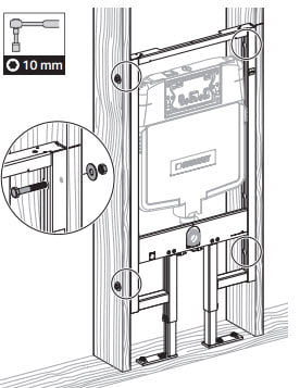
Secure the Geberit In-Wall toilet carrier frame to the wall studs using nuts and bolts or lags bolts.
With this adjustment made, temporarily install the frame into the wall cavity. The frame should fit snugly in the wall cavity with the sides of the frame touching the bordering studs. Use a level to ensure the unit is level and plumb within the wall cavity.
Then, check to brand sure the carrier frame is flush with the forepart confront of the studs. Then, mark the summit tiptop of the frame on the adjoining studs to point the location of to-be-added horizontal framing.
Side by side, install a piece of horizontal ii ten 4 blocking within the wall framing just higher up the top of the unit. Although not required, this horizontal blocking is a good idea, every bit it will strengthen the framing around the unit.
With the horizontal blocking installed, mark the frame mounting hole locations on the top and adjoining studs. Mark the bolt hole locations at the base of operations of the unit also.
Remove the unit and drill holes in the framing at the marked mounting locations. Employ the proper size drill for the fasteners you are using (check the installation documents). Typically, woods framing volition require lag bolts at the base and standard bolts with nuts at the sides (and top if using).
For my install, I used lag bolts on the sides (I had double studs to bite into) and base of the frame and standard bolts with nuts at the top of the frame. If using lag bolts be sure to drill the proper size hole into the wood framing prior to installing the bolts. If the holes are too pocket-size, you tin can crack the framing. If the holes are too large, the bolts may lack belongings power.
If you accept access to both sides of the studs, using bolts may provide a stronger mount.

In one case the frame is secure within the wall crenel, install and connect the outlet (waste) pipage fittings and connections.
Begin past connecting the supplied xc-degree outlet pipe fitting (black in color) to the carrier frame using the supplied, 2-piece clench bracket. And so connect the discharge of this fitting to the stubbed out 3″ PVC waste line using the supplied hubless connector. You lot may take to trim the iii″ PVC waste material line prior to connecting.
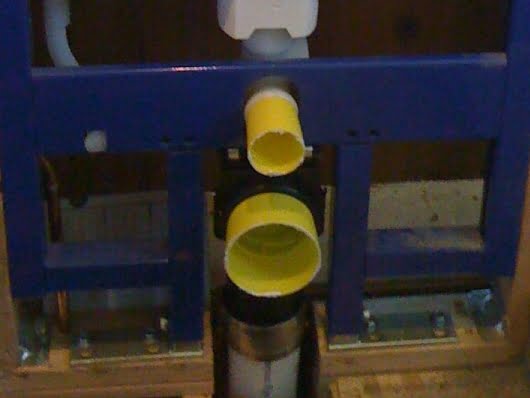
Geberit supplied protective plaster caps.
One time the connexion is consummate, protect the plumbing connection opening by capping them with the supplied yellowish plaster caps. These covers volition keep droppings out and protect the ends of these connections. Apply painters tape if the pre-made covers are non bachelor.
Next, connect the toilet bowl mounting threaded rods to the carrier frame. You will not need to set a particular depth for these mounting rods yet, but screw them into the frame far enough, so they are not in the fashion during the remaining construction. In one case installed, pass the clear plastic tubing thread protectors over the installed threaded rods.


Run cold water supply plumbing to the meridian of the concealed wall carrier unit and connect to the supplied valve. Plan the valve location to allow for the passage of the valve into the carrier unit through capped access hole at the acme left of the unit. Employ drib ear elbow fitting at the finish of the supply line to allow for a secure connexion for the supply plumbing (see photo to the correct).
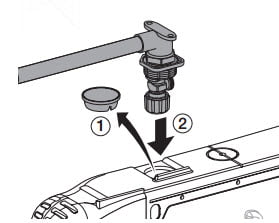
Connect supplied close off valve to 1/2″ supply plumbing then mount so valve is attainable within carrier unit.
Geberit valve assembly and connection to h2o line.
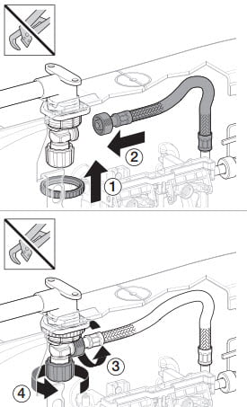
Connect the Geberit supplied supply water valve to the driblet ear elbow (later on applying several wraps of Teflon tape in a clockwise direction when looking at the distal end of the fitting). Then laissez passer the valve into the carrier through the access hole (remove the cap beginning) at the top left of the unit of measurement.
Side by side, secure the drop ear elbow to the wall framing using a block of wood located in a higher place the elbow (see in a higher place rear view of the unit in footstep v). Before mounting the elbow, make sure the passed supply valve outlet is oriented to the right front of the unit to permit for easy connectedness to the water line inside the unit.
With the supply line securely mounted and the supply valve passed into the carrier and properly align, connect the supply valve to the h2o tank within the unit of measurement using the supplied braided stainless steel h2o line.
Afterward connecting the valve end of the water line, purge the line and supply plumbing of air past opening the valve at the end of the continued supply line in a modest pail or container.
When connecting the braided h2o line utilize only paw tightening. These connections use small o-rings seals that can exist torn easily with too much force. Practise not use a wrench on these connections!
Prior to connecting the line, accept a moment to apply a bit of o-ring lubricant to the seals prior to tightening.
Prior to finishing the wall in front of the curtained tank unit of measurement, protect the tank and actuator by installing the supplied splash baby-sit and mud covers.
Both connect to the unit with snapping tabs and notches on the unit of measurement face up plate. Install the splash guard get-go by inserting the lower tabs and then swinging the elevation in until the elevation tabs lock.
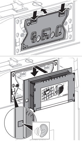
Install the protective splash guard and mud cover prior to finishing.
With the splash baby-sit in place, install the mud comprehend. The mud cover locks onto slots on the front of the front plastic face plate (come across diagram to the correct).
With the unit securely fastened in the wall cavity and the supply and waste plumbing connected, consummate the construction and finishing of the wall over the concealed carrier unit. Geberit recommends sheathing the wall over a concealed toilet tank wall unit of measurement with cement board or similar moisture-resistant sheathing. We used cement board and finished with the same white subway tiles nosotros used for the shower.


With the wall finished, the next job is to connect the toilet bowl to the wall and plumbing.
Earlier we can hang the toilet, nosotros need to insert the plumbing adaptors and seals that will attach to the toilet bowl.
Using the Geberit supplied plumbing connector gear up, we will install fittings for the flush h2o and waste connections. These fittings will need to be cut to the proper length depending on the toilet bowl you are using. Once cut, rubber seals connect to the fittings to form a seal with the toilet bowl.
To mensurate the fittings correctly, follow the instructions provided past the in-wall unit yous are using. I found this installation video useful for accurately determining the proper fitting lengths. The toilet bowl install begins at the 4:10 marking of the video.
Measuring and cutting the plumbing connections is critical. Have your time with this stride and make sure the tubing lengths are correct.
Here is a walk-through of the process to reinforce the video instructions:
i. Find the supplied plumbing connector set with inlet and outlet seals and connection hardware. Remove the protective yellow covers from the upper supply pipe (smaller) and the lower (larger) waste pipe. Apply the supplied lubricant to the inner seals of both pipes.
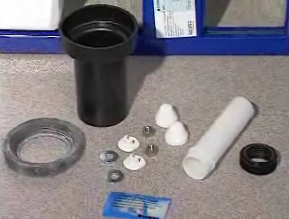
Geberit plumbing connector kit.
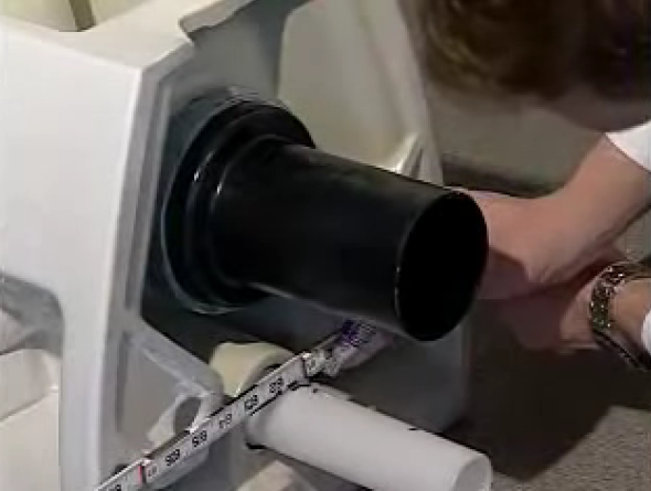
two. Adhere the supplied safety seals to the ends of both the smaller white flush connector and the larger black waste connector. Then, insert both connectors into the pipage openings in the wall with the seal ends out. Gently push button them in as far as they will go. Mark both connectors at the level of the wall face with the marking. Remove both of the connectors.
three. Lubricate the porcelain connection ends at the back of the toilet. Spread the lubricant effectually the inside of the flush inlet (smaller opening) and the outside of the waste outlet (the larger opening).
four. Install the connectors to the toilet bowl for marking. Push the seal ends of the connectors into the toilet basin. The flush inlet (smaller) connector should fit inside the toilet affluent opening, and the waste outlet (larger) connector should fit over the toilet waste product outlet.
5. After both fittings are fully engaged with the toilet basin, mark both connector pipes at the level of the base of operations of the back of the toilet bowl using a directly border and marker. And so, remove both of the connector pipes.
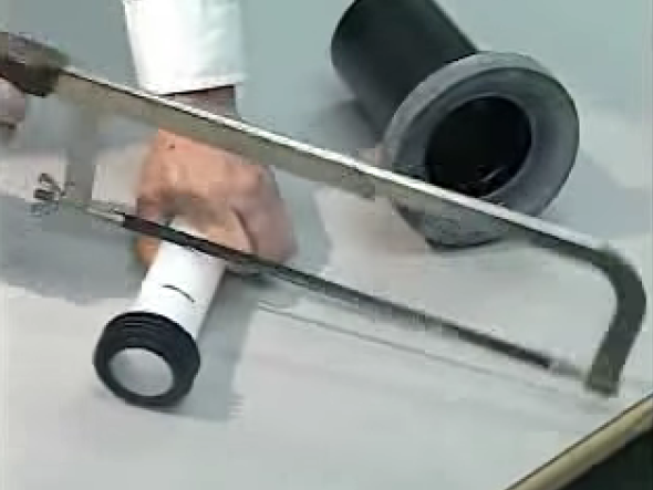
Cutting the plumbing connections afterward measuring.
Advisedly cutting the supplied plumbing connections.
6. Now y'all will have the two connector pipes with two marks on them. Utilize these marks to determine the cut-off signal on the end (non-seal terminate) of the connector pipes.
Do this past:
1) Measuring the distance between the 2 marks on the pipage.
2) Add 1/eight″ to this measured altitude.
3) Mark the location of the above length measured from the not-seal cease of the connector pipes.
iv) Cut the pipes at this mark.
Instance: Y'all pipe has ii marks that are 3″ between. Add 1/8″ to become 3 ane/8″. Measure 3 i/8″ from the non-seal finish of the pipe and cut there.
7. Cut the supply and waste pipes as outlined above. Consider using a method of cutting the pipes that will create a square, flat, cut cease. If using a hand saw, consider using a miter box. In one case cut, smooth the cut border of the pipe at a 45-caste angle with a file or sanding block. Be sure to remove burrs from the cut pipe as they tin can damage the safety seals the pipes volition laissez passer through when installing them.
8. Lubricated and install both connector pipes into the wall unit, gently pushing them in as far every bit they will become.
9. Gear up to install the toilet bowl. Adapt the mounting threaded rods to the proper depth by measuring the thickness of the toilet mounting flange and adding 7/8″ – 1″ to the flange thickness. If using the foam pad (sound guard) behind the toilet, install it now.
10. Install the toilet by lifting it to align the toilet openings with the connector pipes from the carrier and so pushing the toilet into the connectors. When the toilet is seated and to the wall, install the leveling washers, the steel washers and so the nuts over the mounting rods. Earlier tightening the mounting bolts fully, check the level of the toilet bowl and make adjustments as necessary using the leveling washers. Once level, tighten the mounting nuts and cap with the supplied plastic covers.
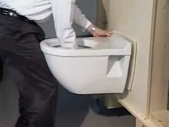
Install the wall-mounted toilet afterward aligning the toilet bowl with the wall plumbing connections.
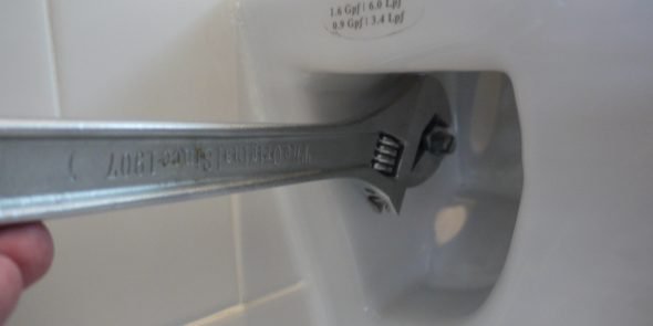
With toilet bowl level tighten mounting nuts.
After the toilet bowl is deeply mounted to the wall, caulk the interface between the bowl and wall with silicone or elastomeric sealant (Lexel).
If using an elastomeric sealant (like Lexel), working very quickly to shine, as this product sets up very rapidly and has a very short working time earlier the surface becomes tacky and hard to smooth.
For a clean caulk line, outset employ painters tape, leaving a gap to apply the caulk. Apply caulk and smooth with finger or tool, and then remove the tape. Next mount a toilet seat designed to fit the toilet bowl you are using. I chose the soft-closing Toto SS204 toilet seat with cover which I highly recommend. Mount the toilet seat using supplied nuts and bolts (nylon in the case of the Toto seat) subsequently adjustment the seat with the basin.


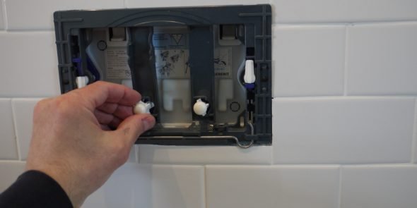
Remove the plaster cover from the actuator access. Snap the walls of the mudguard then they are flush with the finished bathroom wall face. Do this by beginning using a utility pocketknife to cut the edges of the mud guard walls back to the desired breaking depth.
Next flush the flexible water supply line to remove air in the supply plumbing (if not already done). Practise so by disconnecting the distal end of the supply line (continued the tank) and opening the supply valve to purge air. Use a small cup to flush to take hold of any water coming out.
Once flushed, connect the flexible h2o supply tubing to the tank connection. Call back to tighten these connections only as they rely on a relatively minor o-band to seal. With the line connected and flushed, open up the supply valve.

Flush air from water line and connect to tank.
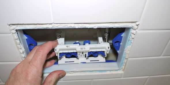
Install the actuator cam lever unit by snapping into frame and tank ledge.
Then, install the affluent components. First, install the actuator cam lever unit of measurement by snapping it into the access base edge lip and resting it on molded ridges on tank.
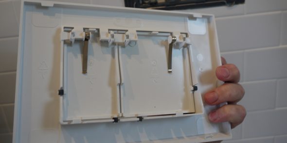
After the cam level unit of measurement is in place, install the white plastic actuator cover plate by inserting the tabs at the bottom and snapping the summit tabs in place.
Next, install the black cover frame using the locking key pins located at the sides of the comprehend. Insert the key pins and turn to lock equally illustrated on the frame.
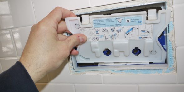
Install actuator cover plate.
Install the actuator frame and flush command push button rods.
With the cover frame installed, insert the flush control push rods into the admission hole in the cam lever unit of measurement. Install one push rod for each flush controller. These rods are notched to allow sizing to friction match the wall depth. To alter the length of these rods, simply break the rod at the advisable notch for the size you need to match your wall depth.
With the control rods properly sized, install them by passing them through the holes in the actuator frame and dust cover and into the actuator "gear box" cams. Some command rods are sized and colored differently for each affluent actuator (bank check with your install literature). Once passed into the actuator gearbox, turn the command rods to lock in place.
Exam the flushing function by pushing on each control rod – information technology should initiate a flush bicycle. With the actuator control rods assembled, locked and working properly, finish the actuator assembly by installing the actuator cover.
Geberit actuator cover plate installs on actuator frame.
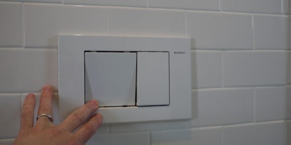
Geberit actuator cover installed.
For the Geberit unit, the cover is installed by first pushing the base of the cover against the wall and sliding upwards to engage the two plastic tabs with the rounded metal springs at the base of operations of the blackness actuator frame. Once both of the lesser comprehend tabs are engaged with the frame spring, push button the cover up and over the height of the frame border to lock in place.
broussardconevenibary.blogspot.com
Source: https://cabindiy.com/how-to/wall-mounted-toilet/
0 Response to "How Do You Know if Toliet Valve Is Threaded or Not"
Post a Comment